Pradyumna Siddhartha and Erick Armbrust
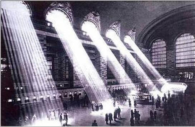
The original photograph
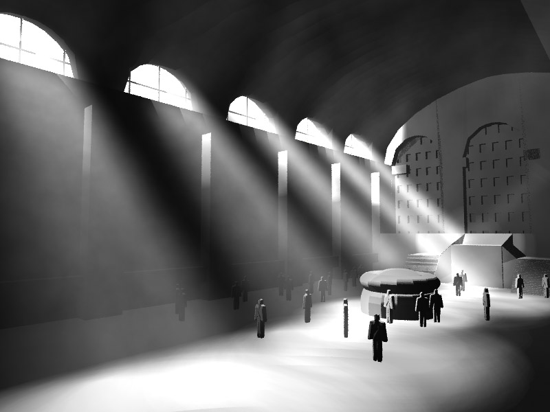
Photon Map rendering of the simplified model, 50000 photons.
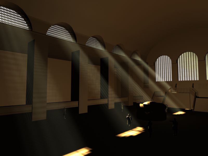
Sample rendering of original model using 3D Studio Max scanline renderer.
The photon map itself is directly based on the book written by Henrik Jensen. The physical structure of the photon map was borrowed from the book so that we could concentrate on the integration of the photon map into LRT's structure. The photon map is essentially just a balanced kd-tree that stores the interactions between light photons and geometry. The actual coupling between geometry and light is removed, however, and merely the level of light deposited and the position is stored.
We had to make changes to the standard LRT lights in order to produce the photon map. The scenes started with a finite number of photons. We enabled the standard point lights to emit photons. Photons were distributed between the various lights in the scene by the actual intensity of the light. We sampled directions on the unit sphere around the point light, and accepted or rejected them based on rejection sampling. Essentially, if a point existed both on the unit sphere and the unit cube within it...it was a valid point. The final photon is then accepted if it intersects an object in the scene...otherwise it is rejected and the sampling is done again. As the photon is traced through the scene...it can do multiple things. If the photon is on its first intersection, it is placed in the "direct illumination" photon map. If it is calculated on a bounce from a diffuse surface (which is determined via Russian Roulette sampling) it is placed in the "indirect illumination" photon map. If the photon is from a bounce or transmission off of a specular surface it is placed in the caustics photon map. Of course, as photons travel through the scene off of specular objects, they pick up the color information of the object. This allows color bleeding to occur within the scene.
The volumetrics for the lights lights were implemented as another photon map. Essentially, if the photon was on its first path (before a diffuse bounce) it has a certain probability of depositing a photon. This probability is based on the absorption constant of the participating medium it is traveling through. After the first absorption the photon is ignored within the haze medium. This is not true in the case of specular elements, however. If the photon is transmitted or reflected...it is still applicable within the medium. This allowed us to create effects such as volumetric caustics.
We had to write an integrator that used the photon map as opposed to the standard integrator. The essential structure of the integrator was the same. The primary change was that when an intersection was found, the irradiance was acquired from the photon map. The irradiance was calculated by getting the values from a certain radius within the photon map. The values that came out of all 3 photon maps were added together to get the final estimate. In addition, ray-marching was executed with the various values being extracted out of volumetric photon map. The radius of the ray-marcher is normalized based on the length of the ray. After the lighting model was calculated via the various photon maps, it was then applied to the intersected object. If the BSDF of the surface returned a specular component, additional rays were traced using the same method up to a maximum depth.
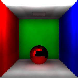
Left: Reflective color bleeding off a metallic red ball (not the red blending with the shadow on a matte white floor).
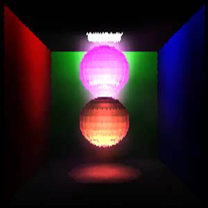
Center: Transmissive color bleeding through two glass spheres (The upper sphere is magenta (1.0,0.5,1.0) and the lower sphere is yellow (1.0,1.0,0.5)) The emitted color is thus red (1.0,0.5,0.5)
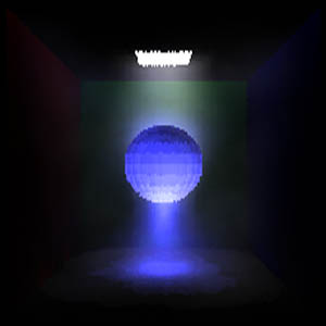
Right: Volumetric caustic produced with white light shining through a blue glass sphere.