After a bit of digging into the subject of spectral rendering, I discovered that there have been several efforts to describe wavelength dependent effects. There are have been different approaches, but most (all?) are based upon converting a traditional ray tracer into a spectrally aware raytracer which recognizes that many values and functions have a dependence upon the wavelength of the light incident to a surface. This causes two main spectral effects, dispersion and thin film interference.
Dispersion is the effect seen with prisms - non monochromatic light is split into monochromatic light (light with energy all near one wavelength). This is due to the fact that the index of refraction for a surface is dependent upon wavelength, and thus the light is bent more or less for different wavelengths, causing the light to split into separate beams. Modeling dispersion requires that a raytracer be modified or built to handle both traditional, smooth spectra and the spiky spectra which is the footprint of monochromatic light.
While dispersion is interesting, I have chosen to model thin film interference, which can be done less invasively than dispersion, and is the effect seen on the bow. Thin film interference is caused by materials which are specularly reflective and transmissive, and have a thickness which is on the scale of the wavelength of light. That is, the thickness of the film is measured in nanometers. Light which reflects off the top of the film and light which is transmitted through the top and reflects off the bottom of the film can interfere, either constructively or destructively based upon the thickness of the film and the spectral wavelength distribution of the incoming light.
There have been two main approaches to simulating thin film interference. One approach, put forth in a paper by Gondek, et al. [3], is to model the electric fields which travel with rays of light and simulate the microgeometry of the surface which causes interference. By simulating the polarization of light, they build a data structure to represent the BRDF of an object with thin film interference. Using this structure during rendering, they can simulate the appearance without needing to analytically solve - or even identify when - thin film interference.
While this is a novel approach, and has several nice features, I have chosen to solve for thin film interference analytically. This requires less knowledge of the structure of the microgeometry of the surface and requires no preprocessing.
My solution was to construct a new material which simulates thin film reflectance. This material has one BRDF which models thin film specular reflection, taking into account interference, and one BTDF which is ideal specular transmission. Solving the equation for thin film interference requires a bit of trick, since the spectrum is represented by three coefficients to three linear, orthonormal basis functions. The outgoing light is a function of the spectral wavelength distribution of the incident light and the distance between the top and bottom of the film. This distance is a function of the thickness of the film and the incident angle, along with the index of refraction of the film.
To solve for this outgoing light, first we convert the spectrum to the CIE xyz format. This gives us nonlinear basis functions, but allows us to sample the distribution at discrete values more easily. We then compute the intensity of the new distribution at each sample point, and use this value to solve for new xyz coefficients using the method described by Bennet and Amezcua [1]. I then convert back to our initial SPD basis functions using the inverse of the matrix of xWeights, yWeights, and zWeights (the matrix used to convert to xyz from the original SPD) from the Spectrum class.
As an attempt at an optimization (and simplification), I created a second thin film material which uses a much uglier method of sampling from the distribution using the original linear basis functions and not the xyz basis functions. While this approach does provide plausible results, it is not as physically accurate, and needs to be know the linear basis functions for the SPD.
Finally, to get all of this working within lrt, I needed to update the integrators I planned to use to perform the interference calculations when the specular BxDF was a thin film. This required the addition of a few methods in the BSDF and BxDF classes, but only a small amount of software engineering. I updated two integrators to take into account interference effects, the Whitted integrator and the photon map integrator. The whitted integrator produces very nice results, with all the strengths and weaknesses of performing Whitted ray tracing. However, the photon map integrator is still buggy, and not all features work properly yet. The biggest bug is that some scenes will cause a segmentation fault. I'm not sure what the cause of this is yet. Secondly, there seem to be some errors with caustics - see the images below for examples. Insuring that all features work correctly and together has been a tough ordeal.
Equally tricky has been setting up a scene and then putting the parameters together in a manner to produce nice images. This is especially exacerbated as the images of the bow often have many layers of translucent material. Thus, it can be extremely computationally expensive to attempt to trace enough layers of the structure to resolve some areas of the image. In fact, due to this cost, I have not attempted to render the normal bow with caustics.
Bowmaker is a program I wrote while working on this project to create all of the bow like objects in the rendered images. The program takes in several parameters describing the physical description of the bow, and uses these parameters to construct a NURBS surface. This surface is outputted as a triangle mesh with per vertex normals in a format which is easy to put into a RIB format. Additionally, the program displays a preview window with the given bow to see the created surface without rendering in lrt.
To build the bowmaker program, simply type make in the bowmaker directory. Use the -h option to view the list of input parameters. The left and right mouse buttons can be used to view the bow from different directions and distances. Finally, the program can use negative values for all parameters. The bows created may not look like bows, but the program will follow the rules and construct objects of some sort.The first images I rendered were of this simple sphere in a box scene. This image is actually incorrect, but was the result of some of the early work and the first time I saw some evidence that I was headed in the right direction.
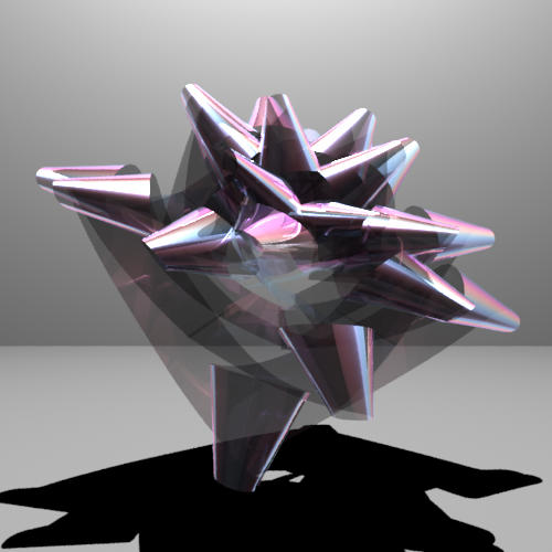
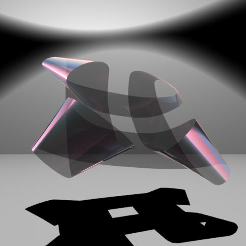
When I finally had things moving in the right direction, I composed this image of a standard bow with thin film interference. This image was done with the Whitted integrator.
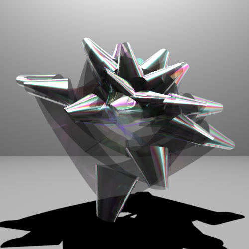
This image is the whitted integrator again, but this time with the optimized, but physically inaccurate thin film material. Still, this thin film material does give the desired effect. Maybe ironically, it is easier to choose parameters which give the desired effect for this material.
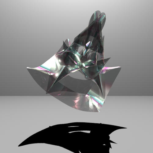
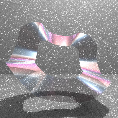
This is an example of the crazier, non-bow like shapes that can be created by the bowmaker program. This is also rendered with the whitted integrator with the experimental thin film material.
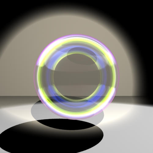
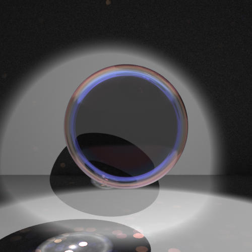
On to the photon mapped stuff. This is the same sphere as from above, only here rendered with the photon mapper. The big problem is that while the indirect lighting (computed with final gathering) looks good, the caustics are a bit noisy. My implementation of photon mapping with thin film interference seems to be the culprit.
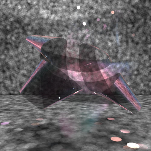
These are some miscellaneous rendered images, not great quality, but showing various bows and some of the thin film interference effects.
Source is provided for bowmaker and lrt files. Rendered scenes are in bowmaker/scenes. Only files changed in lrt are included in the tar.gz file. The Makefile.filelist will need to be changed to build the relevant files. Finally, the better implementation of the material class is in thinfilm-new, while thinfilm is the lower quality version.